The following tables show standard dimensions for keys and their grooves.
Search in blog
Blog categories
Latest posts

Motor Direction

Clearance hole chart for inch bolts and screws according to ASME B18.2.8

One of the earliest forms of comparison. The pigment/binder ratio is the weight ratio of the sum of the pigments...
Popular posts


Featured posts


Blog tags
Photo gallery
No featured images
Archived posts
Top authors
Viscosity Conversion

Dynamic Viscosity
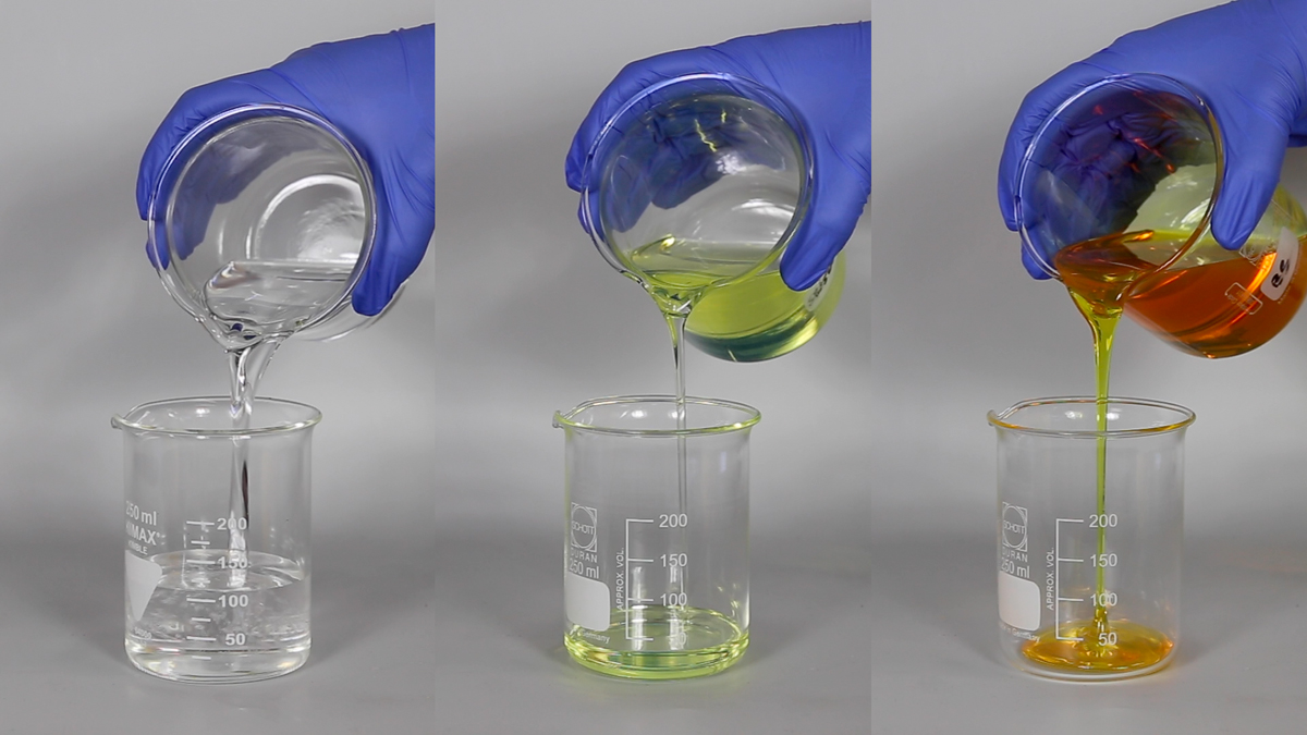
Viscosity describes a fluids resistance to flow. Dynamic viscosity (sometimes referred to as Absolute viscosity) is obtained by dividing the Shear stress by the rate of shear strain. The units of dynamic viscosity are: Force / area x time The Pascal unit (Pa) is used to describe pressure or stress = force per area This unit can be combined with time (sec) to define dynamic viscosity.
Centipoise (cP) is commonly used to describe dynamic viscosity because water at a temperature of 20°C has a viscosity of 1.002 Centipoise. This value must be converted back to 1.002 x 10 -3 Pa s for use in calculations.
Kinematic Viscosity
Sometimes viscosity is measured by timing the flow of a known volume of fluid from a viscosity measuring cup. The timings can be used along with a formula to estimate the kinematic viscosity value of the fluid in Centistokes (cSt). The motive force driving the fluid out of the cup is the head of fluid. This fluid head is also part of the equation that makes up the volume of the fluid. Rationalizing the equations the fluid head term is eliminated leaving the units of Kinematic viscosity as area / time.
The kinematic viscosity can also be determined by dividing the dynamic viscosity by the fluid density.
NOTE: This chart is intended for use in comparing methods of relative viscosity measurements made on Newtonian liquids to absolute and kinematic viscosity. Assumes density is equal to 1 g/cu cm.
| POISE | STOKES | #4 FORD CUP | ZAHN | GARDNER HOLT | KREBS STORMER | ||
|---|---|---|---|---|---|---|---|
| #2 | #3 | #4 | |||||
| 0.01 | 0.01 | A-5 | |||||
| 0.1 | 0.1 | 16 | A-4 | ||||
| 0.15 | 0.15 | 17 | A-3 | ||||
| 0.22 | 0.22 | 13.6 | 19 | A-2 | |||
| 0.32 | 0.32 | 15.3 | 20 | A-1 | |||
| 0.5 | 0.5 | 19 | 22 | A | |||
| 0.65 | 0.65 | 22 | 27 | B | |||
| 0.85 | 0.85 | 27 | 34 | C | |||
| 1 | 1 | 30 | 41 | 12 | D | ||
| 1.25 | 1.25 | 36 | 49 | 14 | 11 | E | |
| 1.4 | 1.4 | 40 | 58 | 16 | 13 | F | |
| 1.65 | 1.65 | 46 | 66 | 18 | 14 | G | |
| 2 | 2 | 50 | 82 | 23 | 17 | H | |
| 2.25 | 2.25 | 55 | 25 | 18 | I | 52 | |
| 2.5 | 2.5 | 68 | 27 | 20 | J | 54 | |
| 2.75 | 2.75 | 74 | 32 | 22 | K | 59 | |
| 3 | 3 | 81 | 34 | 24 | L | 61 | |
| 3.2 | 3.2 | 86 | 36 | 25 | M | 62 | |
| 3.4 | 3.4 | 91 | 39 | 26 | N | 63 | |
| 3.7 | 3.7 | 99 | 41 | 28 | O | 64 | |
| 4 | 4 | 107 | 46 | 30 | P | 65 | |
| 4.35 | 4.35 | 116 | 50 | 33 | Q | 66 | |
| 4.7 | 4.7 | 125 | 52 | 34 | R | 67 | |
| 5 | 5 | 133 | 57 | 37 | S | 68 | |
| 5.5 | 5.5 | 146 | 63 | 40 | T | 69 | |
| 6.3 | 6.3 | 167 | 68 | 44 | U | 71 | |
| 8.85 | 8.85 | 199 | 64 | V | 78 | ||
| 10.7 | 10.7 | 270 | W | 85 | |||
| 12.9 | 12.9 | X | 85 | ||||
| 17.6 | 17.6 | Y | 100 | ||||
| 22.7 | 22.7 | Z | 105 | ||||
| 27 | 27 | Z-1 | 114 | ||||
| 36.2 | 36.2 | Z-2 | 129 | ||||
| 46.3 | 46.3 | Z-3 | 126 | ||||
| 63.4 | 63.4 | Z-4 | |||||
| 98.5 | 98.5 | Z-5 | |||||
| 148 | Z-6 | ||||||
Latest posts

The following tables show standard dimensions for keys and their grooves.

Motor Direction

Clearance hole chart for inch bolts and screws according to ASME B18.2.8

One of the earliest forms of comparison. The pigment/binder ratio is the weight ratio of the sum of the pigments...
Popular posts


Leave a comment
Related posts
 What to consider when moving to an Inverter
 Dual-Axis Centrifugal Mixer - A Better Mix
 JACKETED TANKS AND THERMAL SHOCK
 Disperser Blade Mounting
 DISPERSER CONFIGURATION


Latest comments