The following tables show standard dimensions for keys and their grooves.
Search in blog
Blog categories
Latest posts

Motor Direction

Clearance hole chart for inch bolts and screws according to ASME B18.2.8

One of the earliest forms of comparison. The pigment/binder ratio is the weight ratio of the sum of the pigments...
Popular posts


Featured posts


Blog tags
Photo gallery
No featured images
Archived posts
Top authors
Disperser Blade Mounting
Disperser Blade Mounting

Blade Mounting Sheet
DisperseTech Blade Mounting Sheets
Jacketed tanks/reactors are commonplace in the chemical industry. Many batch operations in the chemical industry require both heating and cooling at different times in the process. Rapid changes in temperature of the heat transfer media can thermally shock the equipment. Typically, thermal shock is defined as changing the cooling or heating media at the jacket inlet more than 25 F per minute. Thermal shock can be avoided by tempering the heat transfer media and providing proper venting. Tempering is easiest achieved when a common heat transfer media is used for both heating and cooling. A Temperature Control Unit (TCU) can be used to adjust the temperature of the heat transfer media at a rate that does not pose the risk of thermal shock. While TCUs are the simplest means of controlling temperature and protecting equipment many companies still insist on using different media for heating and cooling. Many times this includes steam heat and water cooling. If this MUST be done some minimum precautions should be taken.
1. HEATING to COOLING:
When changing from steam heating to cooling water one of the following procedures should be followed:
A. Forced Tempering
Vent steam out of jacket and drain condensate. Allow jacket cool down naturally or use compressed air to blow-down the jacket from top to bottom to achieve correct temperatures. Close vents and slowly introduce hot water at the correct temperature to the jacket. Increase flow rate to process conditions and decrease water temperature at a rate of less than 25 F per minute.
B. Natural Tempering
Vent steam out of jackets and completely drain all condensate. Allow the jacket to cool down naturally to the correct temperature. Close vents and introduce cooling water.
2. COOLING to HEATING:
When changing from cooling water to steam heating one of the following procedures should be followed:
A. Forced Tempering
Raise circulating water temperature in the jacket at a rate of less than 25 F per minute until desired steam temperature is reached. Vent jackets and completely drain out water. Close vents and slowly introduce steam into the jacket.
B. Natural Tempering
Vent and drain water out of jackets. Let the jacket warm up naturally to the correct temperature. Slowly introduce steam into jackets at reduced pressure and/or flow rate (temperature) until the desired steam temperature is reached. As with any manual process, there are risks associated with this.
Mounting Configurations
In order to transfer torque from the mix shaft to the blade, manufacturers use a number of configurations:
CENTER BORE ONLY
A round hole is made in the center of the blade. The blade is sandwiched between an upper and lower surface (this could be a shoulder on the shaft and the retaining bolt or a pair of washers or taper plates). As the bolt is tightened it applies pressure to the blade. It is this pressure that transfers torque to the blade. This design is used on none but the smallest blades, 4" and below. Typically found on aftermarket lab shafts and lab equipment.
- At DisperseTech we use this design for our light-weight lab shafts with blades up to 3" in diameter.
- DisperseTech LLC
- Morehouse Cowles
- Myers Engineering
- Shar Systems
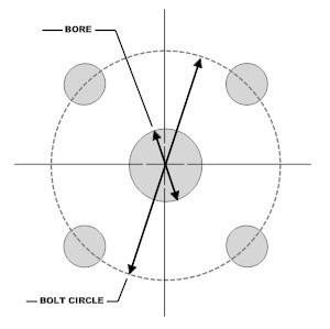
CENTER BORE and PIN HOLES
By far this is the most common configuration. A center hole is drilled in the blade. Two (2), three (3), four (4) or more holes (pin holes) are drilled around the center hole. Drive pins extend from a hub or taper plate through the blade and typically extend into a lower plate or washer. Torque is transferred from these pins to the pin holes in the blade. This design is used throughout the horsepower range and blade size range. As blade diameter increases, the distance between pinholes and/or the number of pinholes is increased.
- Bowers Process Equipment
- Jaygo Incorporated
- Morehouse Cowles
- Myers Engineering
- Schold Machine Corporation
- Shar Systems
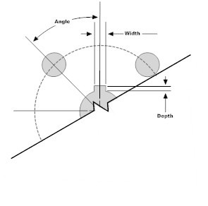
CENTER BORE and KEYWAY
This configuration is primarily promoted by Hockmeyer Equipment Corporation. In this design a keyway is cut into the blade extending from the center bore. The dispersion blade is again sandwiched between a pair of taper plates, which are also keyed. A keyway is also cut into the shaft. Torque is transferred from the shaft through a key to the blade. Typically used through 60 HP with blades up to approximately 18" in diameter.
COMBINATION KEYWAY and PIN HOLES
Unique to Hockmeyer, this design is typically used with machines over 60 HP and blades over 18" diameter, the bore and keyway is supplemented by the addition of 2 or more pin holes.
- Hockmeyer Equipment Corp.
Mounting Arrangements by Manufacturer

Bowers Process Equipment
Bowers produced dispersers in Stratford, Ontario. They make use of a very common design in driving their disperser blades, CENTER BORE and PIN HOLES. Unlike most, they made use of an odd 3 pin holes at 120 degrees. Common bores include
- 1-1/2" Center Hole and three (3) 3/8" pin holes on a 2-1/4" bolt circle
- 2-13/16" Center Hole and three (3) 17/32" pin holes on a 4" bolt circle

Cowles / Morehouse Cowles
Morehouse Cowles manufactures dispersers on the west coast. Their blades are mounted with center hole and pin holes. Some of their common arrangements include:
- 5/8" center hole ONLY
- 5/8" center Hole and two (2) 3/8" pinholes on a 2-1/4" bolt circle
- 5/8" center Hole and four (4) 3/8" pinholes on a 2-1/4" bolt circle
- 3-9/16" center Hole and four (4) 21/32" pinholes on a 4-1/16" bolt circle

Hockmeyer Equipment Corp.
Hockmeyer Equipment Corporation, a disperser manufacturer located in the Carolinas is one of the only manufacturers to use a design consisting of a CENTER BORE and KEYWAY to transfer torque to the blade. The most common of the bore designs for the Hockmeyer Blade include:
- Lab to 3 HP - 1/2 bore with Keyway
- 5hp to 7.5 hp - 3/4" bore with keyway
- 10 to 30 hp - 1-3/8" bore 40 to
- 60 hp - 2-3/16" Bore
- 100 hp - 2-3/4" Bore *NOTE -
- Large HP 2-3/4" Bore may also have (2) 1/2" Pinholes on 8" bolt circle

Jaygo Incorporated
Jaygo Incorporated is based in the North Jersey Area. Their blades are mounted with a center hole and pinholes. The most common of the bore designs include:
- 5/8" center Hole and two (2) 9/16" pinholes on a 4" bolt circle
Myers Mixers
Myers Mixers has been building since the 1940. Myers also uses a center hole and pin hole arrangement. Their most common bores include:
- 5/8" Center Hole and two (2) 7/16" pin holes on a 2-3/4" bolt circle
- 5/8" Center Hole and two (2) 7/16" pin holes on a 3-1/4" bolt circle
- 5/8" Center Hole and four (4) 7/16" pin holes on a 5" bolt circle
- 3" Center Hole and four (4) 9/16" pin holes on a 5" bolt circle
- 3-1/2" Center Hole and four (4) 9/16" pin holes on a 5" bolt circle

Schold Machine Company
Schold is a Chicago based disperser manufacturer. The most common of the bore designs include:
- 5/8" Center Hole and two (2) 1/2" pin holes on a 2-1/4" bolt circle
- 1" Center Hole and two (2) 1/2" pin holes on a 6" bolt circle

Shar Systems Inc.
Shar manufactures dispersers in Indiana. The most common of the bore designs include:
- 3/4" Center Hole and two (2) 5/16" pin holes on a 2-1/2" bolt circle
- 1-3/4" Center Hole and two (2) 5/16" pin holes on a 2-1/2" bolt circle
- 3/4" Center Hole and two (2) 3/4" pin holes on a 3-1/2" bolt circle
CLEAR DIAMETER: The clear diameter defines a circle at the center of the blade free from obstruction. It defines the largest reinforcing disk and/or mounting hub that a blade can accommodate. This is more a property of the blade style rather than the disperser. It is most important for blade styles with louvers, rings, and inset teeth, including:
- Constant Shear Impellers
- CONN Blades
- D Blades
- Myers Style Blades
Visit our blade shop to view various replacement configurations.
Latest posts

The following tables show standard dimensions for keys and their grooves.

Motor Direction

Clearance hole chart for inch bolts and screws according to ASME B18.2.8

One of the earliest forms of comparison. The pigment/binder ratio is the weight ratio of the sum of the pigments...
Popular posts


Leave a comment
Related posts
 What to consider when moving to an Inverter
 Dual-Axis Centrifugal Mixer - A Better Mix
 JACKETED TANKS AND THERMAL SHOCK
 DISPERSER CONFIGURATION
 Tip Speed Definition and Formula


Latest comments