The following tables show standard dimensions for keys and their grooves.

StateMix Planetary Centrifugal Mixer
$0.00


Clearance hole chart for inch bolts and screws according to ASME B18.2.8

One of the earliest forms of comparison. The pigment/binder ratio is the weight ratio of the sum of the pigments...


No featured images


Clearance hole chart for inch bolts and screws according to ASME B18.2.8
One of the earliest forms of comparison. The pigment/binder ratio is the weight ratio of the sum of the pigments...
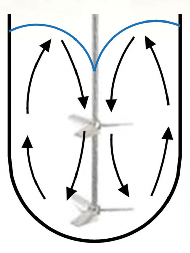
Fig. 1: Axial Flow in a Single Shaft Mixer
The single-shaft mixer has limited use in the preparation of adhesives and sealants, as the axial flow patterns are difficult to reproduce in the high viscosities these products typically exhibit. When viscosity rises, mixing efficiency drops as the distance from the mixing blade increases. Increasing the blade speed does little to compensate for the loss of flow at the outer reaches of the tank. In addition, vortexes become deeper as speed increases, resulting in air entrainment. To overcome these limitations, multiple shafts were introduced to provide both the shear and flow necessary to produce a uniform product. Multiple-shaft mixers are common in the production of adhesives and sealants. However, these multi-shaft mixers do not produce the same flow patterns. They also require additional clean-up, limit the ability to produce small batches, and do not always mix as efficiently in small sizes as larger production machines. In many cases, the only option available has been to manually assist the mixer or manually mix all together.
The dual-axis centrifugal mixer uses no shafts. Instead, it relies on two distinct rotational vectors and angular alignment of the mixing container to produce its mixing ability (see Figure 2). First, a mixing container is held at a fixed distance from a center axis; the container orbits that axis at high speed. (If this were the only axis of rotation, the unit would effectively operate as a centrifuge, separating products based on density.) To complement this motion, the container rotates about its own center axis and the cup is angled toward the motor axis. This second axis of rotation and cup angle is essential to the generation of the mixing action. Figure 2: Interior of a Dual-Axis Centrifugal Mixer
The surface of the water in a cup remains perpendicular to the force of gravity, acting on it regardless of the angle at which the cup might be held. The surface of the material in the mixing container will remain perpendicular not to the force of gravity, but to the stronger centrifugal force created by the orbital speed of the container. The centrifugal force is a function of the distance from the center of rotation and the angular velocity. The dual-axis centrifugal mixer develops centrifugal acceleration in the range of 400 G. Due to the angle at which the cup is held, the distance between the center machine axis and any point on the surface of the product continually changes as the cup rotates. Product flows to compensate for these changes, resulting in flow patterns from the edge of the container to the center of the batch.
The mixing action of the dual-axis centrifugal mixer can be demonstrated with white and blue samples of children’s modeling compound. Approximately 80 grams of the blue and another 80 of the white were rolled into a ball, flattened into “hockey pucks” and placed into the mixing cup, with blue on the bottom and white on the top. The flow pattern observed in a traditional single-shaft mixer includes a vortex in or around the center of the mixing container.
[caption id="attachment_637" align="aligncenter" width="300"] Figure 3: Surface Flow Pattern[/caption]
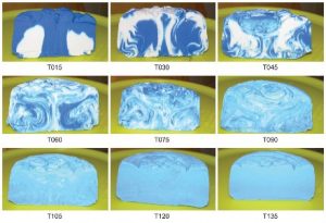 Figure 4: Internal Flow Pattern[/caption] After T015 (15 seconds), the blue material, which was originally at the bottom of the container, has traveled up the wall of the vessel, across the top, and down the center of the product. By T030 (30 seconds), a mixture of blue and white material follows a similar path. This mixing continues until T135 (2 minutes, 15 seconds) when a uniform product is produced.
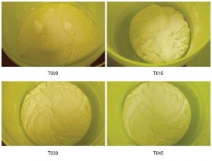 Figure 5: Powder, Paste and Liquid Mixing[/caption] The dual-axis centrifugal mixer produces the axial flow patterns that are predominant in liquid mixing while overcoming the viscosity limitations of a traditional single-shaft mixer. Added benefits include reduced cleanup requirements, as all shafts are eliminated and the container remains the only contact part. Without shafts, it is possible to produce very small batches; standard units are capable of mixing batches as small as 50 grams and as large as 2,500 grams. (These batch limits can be extended with container adapters.) In addition, the shallow vortex eliminates additional air entrainment during mixing. As vortex depth is not a limiting factor, the dual-axis centrifugal mixer can mix at high energy levels, which results in shorter batch times. In the adhesive and sealant industry, the mixer has been used for fast and efficient formulation qualification, pilot development, and small batch production.
Schmidt, Stephen T. "A Better Mix" Adhesive & Sealants Industry Magazine, 1 July 2010.
 What to consider when moving to an Inverter
JACKETED TANKS AND THERMAL SHOCK
Disperser Blade Mounting
DISPERSER CONFIGURATION
Tip Speed Definition and Formula
What to consider when moving to an Inverter
JACKETED TANKS AND THERMAL SHOCK
Disperser Blade Mounting
DISPERSER CONFIGURATION
Tip Speed Definition and Formula


Latest comments